Splicing wires together is a fairly simple task. The problems caused by wire splicing is that generally most people opt to use low quality “crush” style but-connectors. These are arguably the worst way to splice wires. A much more reliable and fool-proof way is to solder them. I typically recommend soldering when connecting wires together permanently, however if you’re hooking up a connector, then I recommend crimping the connector properly if possible.
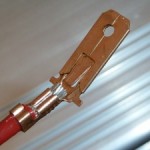
A note on crimping vs soldering: “Proper” crimping techniques are as good if not better than soldering (it’s what the OEMs use) however to crimp properly requires that you have the proper crimping tools and proper crimp connectors. Using a crappy plastic covered but-connector with a “tool” that just squishes it is garbage; and should be avoided at all costs. If you’re unfamiliar this is what a proper crimp looks like:
 this is what a bad crimp looks like:
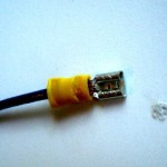 Bad crimps will fall apart, cause weak connections, look bad and will in general cause you far more headaches, frustration, and problems than they’re worth. Most of the time when someone comes to me looking for help fixing electrical issues, it’s because they’re using crappy crimp connectors like the yellow one above.
Proper crimping is generally faster and easier than soldering, but it’s more expensive as it requires more expensive tools and consumables.
What you will need to solder splice:
- Wire – If you’re extending existing wire make sure you use the same type (solid or stranded), the same color and the same gauge (this is the wire diameter) of the wire you’re splicing with. if you’re unsure of the gauge and type most automotive wire is stranded 18 or 16 gauge for data and signal wires if you’re doing power wire (such as relay/fuse blocks) you may want to consider heavier gauge such as 14 or 12 gauge or even larger depending on how much amperage will be going through the wire. You can determine the Amperage based on the fuse used on that circuit (which will generally be 2-3 times higher than the actually amperage the line typically sees). You can use this chart to determine the appropriate gauge to use on your power circuit.
- A soldering iron – The best type of iron you can buy is a “soldering station” style iron with adjustable temperature and a “magnetic tip” These can regulate the iron temperature precisely and make soldering much more enjoyable. You can typically pick these up for about $45 I usually solder 16-18 gauge wire around 400-450 deg F, and then go warmer I’m working with heavier gauges. If you can’t afford that I recommend picking up a cheap pencil type 30W iron from Radio Shack (higher Wattage irons are generally TOO hot unless you’re working with 12 gauge or larger wire).
- Solder – pick up some “rosin core” solder with a decent 0.032” diameter this type of solder has material in it that makes the solder stick to the wires better and makes your life easier. You can usually find this at Radio Shack.
- Heat Shrink Tubing – Buy some appropriately sized head shrink tubing. Ideally you’ll want something water proof and mailable. I’ve found the black heat-shrink sold at Home Depot works fairly well. The package should tell you what gauge wire the tubing is good for.
- Heat Gun – You’ll need a heat gun to shrink the tubing. Some people use a lighter or a small butane torch, but you run the risk of over heating the tubing and burning it or damaging the wires so it’s not recommended.
- Wire Strippers – you’ll need this to strip your wire, in a pinch you can get away with using a set of sharp cutters. I personally recommend a simple stripper with various size teeth for different sized wires such as these. I tend to avoid the automatic strippers where you insert the wire into the mouth and strip a wire with a single pull as I feel you don’t have good control over over the strip.
- Multimeter (optional) – This is good to help you check your work but isn’t really necessary for jobs that can be done on a bench or have a small number of wires. It’s much more important if you’re working with harnesses while they’re in the car or dealing with lots and lots of wires.
Step 1. Start by stripping about 1/2 inch of wire from either side of the wire you plan to splice
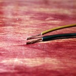
Step 2. Cut about 1 inch of heat shrink tube and slide it over one of the wires. slide it down far enough that it wont get hot when you solder.
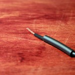
Step 3. Cross the tips of the wires you’re splicing to make an X, make sure they cross about 2/3rd of the way down the spliced area (so more near the base than the tip). Then twist them together tightly as if they were two arms folding.
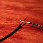
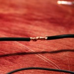
Step 4. Solider the wires together. You’ll want to make sure the iron has fully warmed up (higher quality irons will have a beep or a light indicating that it’s up to temp. You should wait 3-5 minutes for cheaper irons to reach temp). Once it’s warm clean the tip of the iron by rubbing it quickly and gently against a damp sponge.
To solder hold the tip of the iron against the exposed wire for a few seconds heating it up. Then melt the solder into the hot wire. It’s ok to get some solder on the tip of your iron but you should never apply the solder directly to the iron. Melt as much solder into the joint as you can so that all of the overlapping areas are coated in a silver color from the solder.
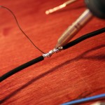
You’ll want to do this quickly (within a few seconds) and then remove the iron, as over heating the area will make it more difficult for the solder to adhere and risk melting the casing of the wire. If it takes more than 2-3 seconds to warm the wire enough for the solder to melt then your iron is too cold. If the solder doesn’t solidify within 1 second of removing the iron then your iron is too hot, or you stayed on the joint too long. This doesn’t need to be done in one application; it’s ok if you use the iron 2 or 3 times on the same joint to get good coverage as long as you wait for the solder to solidify before re-applying the iron. It’s also a good idea to clean the tip of your iron every-time you remove it from the joint.
Once you’re done clean the iron off again by rubbing it quickly and gently against the damp sponge to remove any solder. Leaving hot solder on the tip will damage the coating on the tip and cause solder to stick to the tip of your iron instead of the wires in your joint.
Step 5. Repeat up through step 4 for all wires in your given bundle before moving on to this step. Once all your wires are soldered, slide the heat-shrink tube up over the joint so that it covers the joint completely and is evenly spaced on both sides. Then put your heat gun on medium heat and warm up the shrink tube. You may have to move the heat gun around a bit to get good even warmth on all areas of the tube. Once your done it should look like the image below.
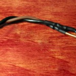
The shrink tube should be snug around the wire and formed to the contour of your solder joint. If it’s not you either didn’t get it warm enough or your shrink tube was too large. Also check to make sure there is no exposed metal anywhere. If there are problems you can wrap the joint in electrical tape, or cut off the heat shrink desolder the wires and start again.
Other considerations:
- If you’re making a harness I recommend wrapping the wires together using electrical tape every 8 inches or so, then covering all of the wires with properly sized wire loom and wrapping the wire loom on the ends with electrical tape as well as every 8 inches or so to help keep the wire inside the loom.
- If you’re splicing 3 wires together with a single joint the process is the same, except one side of the joint will be two wires next to each other. I would also recommend stripping off a little more of the casing on each of the wires, try to slide the heat shrink tubing over the side with two wires as this will help keep them together and helps you make sure the tubing is large enough. Ideally however you should avoid making splits mid-wire, instead make splits at connectors right at the pin crimp, this makes it easier to track the path of the wire down the road.
