LS1 AC Wiring
Filed Under (Engine, LS1) by Michael Pica on 14-03-2010
Tagged Under : Air Conditioning, conversion, Wiring
I just went though the wiring for AC on the Vette and the Camaro into an S14… it’s actually pretty simple.
The HVAC electrical diagrams for the S14 span 6 pages, the Vette diagram doesn’t even fill 1.
Components needed
-LS AC compressor (duh)
-LS AC Pressure Sensor (might want to get the line it attaches to as well)
-An AC Relay (the Factory Relay in your S-chassis will do just fine)
-Your ECU needs to be programmed for a “Manual HVAC” setup (not “Automatic”)
This wiring works for engines sourced from LS1 equipped Corvettes, Camaros, and Firebirds.
1. AC Compressor has 2 pins: One for 12V and one for ground, this is switched on by the Relay. What you’re doing here is simply cutting off the S14 AC connector ( on the drivers side near the steering rack) re-routing to the right side of the bay and soldering on the LS connector.
-Pin A on the LS connector is Dark Green and replaces Pin 1 on the S14 Compressor Connector E46 which is Yellow with a Red Stripe (switched 12V source)
-Pin B on the LS connector is Black and replaces Pin 2 on the S14 Compressor Connector E46 (ground)
2. AC Pressure Sensor has 3 pins, a ground reference, a 5V reference and an output signal, all 3 feed directly into the LS harness and directly to the ECU
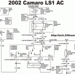
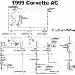
-Pin A on the LS connector for the Corvette it is Black and goes to Blue#60 on the ECU harness, for the F-Body it is Purple and goes to Red#57 on the ECU harness (Ground Reference)
-Pin B on the LS connector is Gray and goes to Blue#45 on the ECU harness (5V Reference)
-Pin C on the LS connector is Red with a Black Stripe and goes to Red#14 on the ECU harness (Sensor Signal)
3. There are a few connections at the F3 plug, allowing easy integration with the S14 for turning on/off ac F3 pins are based on the diagram here: http://forums.240sxone.com/showthread.php?t=7091
-Pin 32 on the F3 connector is Yellow with A Black stripe and goes to Red#17 on the ECU which is Dark Green with a White stripe (AC On signal from HVAC)
-Pin 43 on the F3 connector is Black with a Pink stripe and goes to Red#43 on the ECU harness which is Dark Green with a White stripe (Compressor Relay turn on signal)
-Pin 44 on the F3 connector is Blue with a Red stripe and goes to Red#18 on the ECU harness which is Dark Green (AC Clutch Status)
4. The Triple pressure switch found on the S14 Dryer isn’t needed for the LS AC setup so it needs to be bypassed, this is located near the battery tray.
-S14 connector E29 Jump pin 1 (Black with pink Stripe) to pin 4 (Green with Yellow Stripe), the other 2 pins can be left as is, one goes to the F3 plug and isn’t used, the other goes to ground
*Note: there are about a dozen other AC related pins on the F3 plug, none of these are needed so you can just de-pin them to clean up the plug.
For Reference here are the FSM Diagrams for the F-Body and Y-Body

