S14 How To: Build an Amp Bypass/Delete Harness
Filed Under (S14 Specific) by Michael Pica on 07-05-2008
Tagged Under : Amp, Audio, Harness, s14
Those who own S14’s with the factory CD player also have to deal with the factory installed Clarion amplifiers in the trunk. The existence of these amplifiers make installing an after-market stereo somewhat of a pain. Since the amp is made by a name brand and tuned specifically for the factory speakers, it’s actually in your best interest to leave it be, even if installing an aftermarket head unit. When doing so it’s advised that you use the pre-amp outputs of your head unit and NOT the speaker outputs that normally connect to the factory harness. You’ll want to look for an “amp integration” type harness when utilizing the factory amplifier and not your head unit’s internal amplification.
Those of us, like me, who wish to replace the factory speakers are actually better off removing the factory amplifier in lieu of amplification from the head unit or through a stand alone aftermarket amplifier. Unfortunately there isn’t a single company on the market that makes an “amp delete” or an “amp bypass” harness. Sure they exist for other cars, but not premium sound system equipped Nissans. This leaves most people with limited options.
Option A: Cut the factory amp harness and splice the inputs and outputs together. Leaving you unable to re-install the factory equipment.
or
Option B: Don’t even use the factory wiring and run your own wiring throughout the car. Adding a ton of extra work and adding more unnecessary weight to the car.
I’m going to give you an Option C… build your own amp bypass/delete harness. Utilize the factory wiring, and retain the ability to re-install the factory amp if you so desire. Another benefit to this is the by-pass/delete harness can be modified down the road as an amp-integration or cross-over integration harness, saving you a lot of work running wires.
Tools Needed:
- Soldering Iron
- Some kind of desoldering tool (desoldering iron, pump, or wick)
- #2 Phillips screw Driver
- Wire Cutters/strippers
- Optional: Multimeter
- Optional: Helping Hands
Supplies Needed:
- An extra Factory amp set (can be out of any Nissan that uses a similar amp, it also doesn’t need to be functional as long as the connectors aren’t physically damaged)
- 20Ga Wire
- Electrical Tape
Step 1: Disassemble the Factory Amps
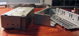
The amps are easy to take apart. there are numerous screws holding the mounting brackets to the amps and holding the amps together. Simply remove every screw that is visible from the outside of the amp. Once they’re all removed the Amp housing should come apart into 2 pieces and completely detached from the circuit board inside.
Step 2: Desolder the Connectors
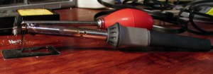
Use your desoldering tool of choice to desolder the connectors from the circuit board. Also note that the metal shielding of the connectors is soldered in 3 places, this will give you the most trouble. If you don’t have a tool at your disposal I highly recommend buying a desoldering iron from Radio Shack. They’re relatively cheap and are far and wide superior to any other desoldering tool under $200.
Step 3: Prep the Connectors
I straightened all of the pins on the connectors and then trimmed them down to roughly 5mm each. The idea was to leave enough length that they were easy to solder to, but make them short enough that they wont easily bend to make accidental contact with one another.
Step 4: Wire the Connectors
The when looking at the back of the connector with the screw hole to your left the pinout is as follows.
 1.LCH(+)IN  | 2.LCH(-)IN
 3.RCH(+)IN  | 4.RCH(-)IN
 5.LCH(+)OUT | 6.LCH(-)OUT
             | 8.RCH(-)OUT
             |10.RCH(+)OUT
11.ACC       |12.GND
13.ON/OFF    |
15.TWL+      |16.TWL-
17.TWR+      |18.TWR-
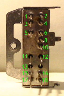
The front and rear amp connectors are identical except the rear amp connectors are missing pins 15-18. For the sake of this project you only need to worry about pins 1-10 everything else on the connector is either not necessary for this mod, or not used by the S14. I recommend leaving the unneeded pins in-tact though, as they would be quite useful in other projects down the road.
You’ll want to make the following connections:
Pin1<->Pin5
Pin2<->Pin6
Pin3<->Pin10
Pin4<->Pin8
In general you’re connecting the “input” wires to the “output” wires as if the amp didn’t exist and the signal goes right through it. you’ll need to make these connections for both the front and rear amp connectors.
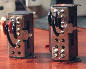
To make the connections heat up each pin on the connector and coat them with solder. Then cut small bits of wire and strip both ends, to make a jumper that will reach from one pin to the other, heat up both stripped ends of the wire and coat them with solder. Finally solder the wire in place connecting the appropriate pins (a set of helping hands is quite useful for this step). Make sure that you don’t bridge any pins together, and that you didn’t accidentally solder the pin to the metal shield of the connector. Also make sure that there is a nice solid connection between the pin and the wire.
Step 5: Test and Protect
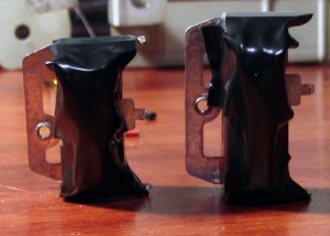
Once you’ve got it all soldered up, inspect it for errors, double check your pins match the pinout above and that no two adjacent pins are connected, if you have a multimeter it’d be a good idea to double check everything with it. Once you’re confident that everything is done right wrap all of the connections in electrical tape to make sure that none of the pins make contact with other electrical objects in the car.
Congratulations, you’ve made a really simple amp-bypass harness, now your factory wiring is intact. Don’t ask me my why no company makes these to sell, it would be quite easy for them to do… as you can tell it’s fairly easy to build yourself as long as you’ve got the tools and parts.
