Which Intake to use:
The Factory intake piping likely wont fit in your S-chassis, Some aftermarket GTO setups might work with a little modification but it’s so easy and relatively inexpensive to just piece together your own that there’s no good reason not to.
There are three different setups that are relatively easy to go with, I’ll will discuss all three.
Designing the Intake:
Since the battery is on the right hand side of the car and the air-box was originally on the left hand side, the best place to put the filter is over on the left hand side.
Clearance between the intake piping and the radiator is quite tight, this is one of the reasons that it’s recommended that you use a Radiator designed for a KA motor, it’s relatively thin for extra clearance and the upper inlet is over on the right hand side of the car and away from the intake system.
There are three different setups you can go with, really it’s your build and you could get even more creative if you like, but these three are straight forward and easy to piece together.
Intake type 1: Shorty
The LSx computer is pretty customizable, you can disable the use of the MAF sensor as well as the Intake Air Temp (IAT) sensor. You can get away with this since the LSx has a MAP sensor at the back of the intake plenum. In doing this you can place a short, wide, oval shaped filter directly over the throttle body. This really doesn’t have any performance benefits but if you’re building a show-car it does help a lot with engine clean up since you’ve got no pipes, and you can cut out two sensors and their associated wiring. You could probably build hood scoop or duct over the filter to drive air directly down on it if you liked. Obviously this is the cheapest option since it has the fewest parts.
Intake type2: Short Pipe
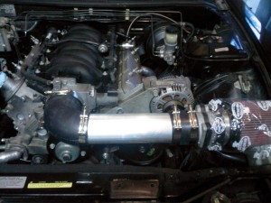
This is probably the most commonly used setup in these swaps. It includes an elbow, a length of straight pipe a straight coupler and a filter along with some clamps.
The setup Pictured above is a Corvette LS1 on which the throttle body has a 4 inch OD and the MAF has a 3.5 inch OD I purchased the couplers, clamps and tubing from IntakeHoses.com and a K&N filter at a different store. my parts list was as follows:
- 1x #90HL40R35 – Reducing Elbow 90 Degree 4″ ID to 3.5″ ID
- 1x #AL35X12 – Aluminum Intake Tubing 3.5″ OD x 12″ Long
- 1x #50194 – Rubber Straight Sleeve 3.5″ ID x 3″ Long
- 3x #94100-0400 – T-Bolt Clamp for 3.5″ ID Black Rubber Intake Hoses
- 1x #94100-0450 – T-Bolt Clamp for 4″ ID Black Rubber Intake Hoses
- 1x #RE-0905 – K&N 3.5″ Universal High Flow Cone Air Filter
This setup fit up and looks great, I did have to trim down the aluminum pipe a few inches as it was too long. Alternatively you could go with a 4″ elbow, and a 4″ to 3″ straight through reducer, but the setup I listed above is a bit cheaper and gives you more room to work with without hindering your performance at all. Another option would have been to go with a 6″ piece of aluminum tubing and a longer filter. The parts list above ran me $122 including shipping charges. Which isn’t all that bad when you consider the cost of most performance intake systems.
You may need to purchase different sized tubing and couplers depending on your MAF and throttle body sizes, as they vary depending on which vehicle you sourced your engine from.
Also note that the IAT will need to be installed somewhere. With the setup above you could either drill a hole in the rubber elbow and squeeze it in there, you could drill a hole in the aluminum tubing and mount it there with a rubber grommet, or some other solution.
Intake type 3: Cold Air
The third option is to build on to the intake style mentioned above, but move the filter down lower to the ground and outside of the engine bay. On the left hand side below your filter there is a hole that leads down into the fender well, part of the original intake was located down here. Some have cut out this opening to make it larger, and then added another bend and short piece of tubing before the filter. This places the filter outside of the engine bay and behind the openings in the front bumper. The result is a little bit more intake piping but air that is cooler and has better flow into the filter.
You could expand on this by adding some ducting from the bumper to the filter. As with all Cold-Air-Intake setups you should be weary of water ingestion, the last thing you want is to trash your motor accidentally driving through a puddle. There are products that help reduce this threat but I wont get into them here.
Because this setup requires some modification to the chassis and can vary depending on how you’d like it to be setup I wont get into a parts list or any additional details but know that it’s an option and relatively straight forward to piece together.
